
Topic:
- What is the meaning of the ESCON PWM input frequency?
- Is there any dependency in between the PWM input frequency (of the set value) and PWM output frequency (of the power stage)?
Solution:
There is no(!) dependency in between the PWM input frequency and the PWM output frequency of the ESCON. Both have separate specifications.
- A PWM input signal in use as the set value can command the ESCON's current or speed control.
The PWM input in use as a set value is typically in use if the ESCON is commanded by a microcontroller which might have no analog output signal but almost ever a PWM output. - The PWM output provides a so-called pulse width modulated voltage with a fixed high frequency (53.6 kHz) to the motor by the ESCON's power stage. This motor voltage adjusts the motor's speed and current.
Technical aspects:
I.) PWM set value input
- The PWM signal which is applied to ESCON's digital input 1 has to fulfill the following specification (see chapter "Digital input 1" of the ESCON's "Hardware Reference"):
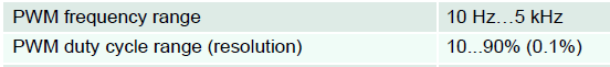
- Restriction 1: 10 Hz ... 5 kHz
- If the PWM's signal frequency applied to the digital input 1 is higher than 5 kHz, the measured PWM duty cycle gets more and more inaccurate and faulty. Therefore take care that 5 kHz is not exceeded.
- If the PWM frequency is too low, the maximum measurement period of the duty cycle is exceeded and the reported PWM duty cycle is also wrong.
- In case of a wrong or less precise PWM duty cycle measurement the motor speed or motor current is controlled and adjusted based on the measured misleading set value.
- Impact of the PWM input frequency?
Please be aware that the PWM input frequency in use also determines how fast updated set values can be identified and processed because one period has to measured before the PWM duty cycle can be determined. High PWM input frequencies mean shorter periods and a more dynamic reaction on any set value change.- In case of the minimum PWM input frequency of 10 Hz each measurement lasts 100 ms before an updated set value can be determined and processed by the control loop.
- In case of the maximum PWM input frequency of 5 kHz each measurement last just 0.2 ms before an updated set value can be determined and processed by the control loop.
- A good compromise in practice offering fast reaction and precise duty cycle measurement is to use 1 kHz which needs 1 ms for signal processing.
- Restriction 2: Duty cycle range 10% ... 90%
- The PWM signal has to be in the range of 10% ... 90% to clearly identify if there is actually a PWM signal present or just an (invalid) constant signal.
- If the measured PWM duty cycle is less than 10% or higher than 90%, ...
- ... the virtual LED "PWM Input Limitation" of ESCON Studio's "Controller Monitor" is activated.
- ... the speed does not decrease below the 10% value resp. does not increase above the 90% value. The resulting speed / duty cycle curve will look like this:
- Resolution of the PWM duty cycle measurement?
- The PWM set value has a resolution of 0.1% resp. 800 resolution steps in between 10% ... 90%.
Example 1: 10% = -5000 rpm / 90% = 5000 rpm
=> Speed resolution for commanding: 12.5 rpm
Example 2: 10% = 0 rpm / 90% = 5000 rpm
=> Speed resolution for commanding: 6.25 rpm
Example 3: 10% = -2000 rpm / 90% = 6000 rpm
=> Speed resolution for commanding: 10 rpm
- The PWM set value has a resolution of 0.1% resp. 800 resolution steps in between 10% ... 90%.
- Error state in case of wrong PWM input frequency or a far too low / high Duty cycle
- The "PWM Set Value Input out of Range Errror" is just triggered when the frequency gets lower than 5Hz, which is also a fact in case of 0% and 100% because there is constant 0V resp. a high level present, i.e. no signal frequency anymore.
- The "PWM Set Value Input out of Range Errror" is just triggered when the frequency gets lower than 5Hz, which is also a fact in case of 0% and 100% because there is constant 0V resp. a high level present, i.e. no signal frequency anymore.
- Precondition for perfect operation
- Please ensure that a PWM signal with a valid frequency and duty cycle is applied before the ESCON is enabled. Otherwise the motor might run at a different speed than expected or there might be even an error state immediately present.
II.) PWM output of the power stage
- The PWM voltage output of the power stage has a fixed frequency of 53.6 kHz.
This is specified by the data sheet and ESCON's "Hardware Reference" too:
III.) ESCON's control frequencies
- The fixed control loop frequencies in use are also specified by the ESCON's "Hardware Reference":
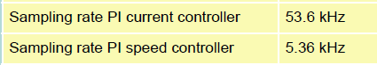
- The PI current controller sampling rate specifies how fast (resp. how often) the current control loop calculation is processed and an adapted motor current is applied. The fix current control frequency of 53.6 kHz means that this calculation is processed every 0.0186 ms.
- The PI speed controller sampling rate specifies how fast (resp. how often) the speed control loop calculation is processed and an adapted motor voltage is applied. The fix speed control frequency of 5.36 kHz means that this calculation is processed every 0.186 ms.
- The control loop frequencies are fix and there is no dependency or correlation to the frequency in use by the PWM set value input.
Comments
0 comments
Article is closed for comments.