
Preface:
maxon motors are very efficient. This is also true when operated as generators. The basic calculations are very simple, not the least due to the linear behavior of motors with slotless windings (maxon DC and long cylindrical maxon EC).
For motors with slotted windings (EC flat motors and EC-i motors), the results are valid as well, as long as the operation is within the limits of the continuous operation range. At high speed and torque values the deviation from this simple theory can be important.
1 DC motor as generator
Brushed DC motors can be used as DC generators. The underlying physical principle is the law of induction. Rotating the motor shaft moves the winding segment through the sinusoidal varying magnetic flux in the air gap. Accordingly, a sinusoidal voltage is induced in each segment. The brushes quasi rectify the induced voltages resulting in a DC voltage at the motor terminals. In reality, the DC terminal voltage shows a slight ripple of a few percent depending on the number of commutator segments (see e.g. the technical data of the maxon DC Tacho DCT 22).
1.1 Basic equations
Driving the motor shaft, a voltage proportional to the shaft speed is generated in the motor
where
- Uind = Induced voltage (V)
- kn = Speed constant of the motor (rpm/V)
- kg = Generator constant of the motor (V/rpm), i.e. the inverse of kn
- n = the speed (rpm)
Figure 1:
DC motor as generator: Electrical layout.
Generator equation
For the unloaded generator, one obtains Uind as a DC voltage at the motor terminals.
If the generator is loaded with current, the voltage drop due to the motor resistance (winding and brush system resistance) reduces the terminal voltage Ut. For a given load current IL, you get
where
- Ut = Voltage at the terminals of the motor-generator (V)
- Rmot = Terminal resistance of the motor (Ω)
- IL = Load current (A)
Figure 2:
The voltage-current-line of the generator.
The electrical power in each point of the line corresponds to the area of the rectangle under the line.
This equation represents the relation between the generated voltage Ut and the load current of the generator at given speed n, i.e. at fixed internally generated voltage Uind.
Graphically, we can call this the voltage-current-line of the generator. It looks very similar to the speed-torque line of the motor. However, …
- ... the current taking the role of the torque, and vice versa.
- ... the speed and voltage taking each other’s role.
- ... the resistance taking the role of the speed-torque gradient
Therefore, for a given motor type, each winding has a different gradient (see Figure 9).
Short-circuited terminals: Maximum current
The maximum possible load current occurs with short-circuited terminals. The only active resistance is the internal motor resistance and the maximum current is
This situation corresponds to the lower right end of the voltage-current-line, where the terminal voltage vanishes.
Open terminals: Without load
In case the motor terminals remain unconnected, no current can flow and the terminal voltage Ut equals the generated internal voltage Uind., i.e. the terminal voltage is proportional to the motor speed. This situation corresponds to the left end of the voltage-current-line. Typically, a DC tacho works close to these conditions (see chapter 3.4) corresponding to a very high load resistance.
Speed and voltage
Increasing the generator speed n shifts the voltage-current-line in parallel towards higher voltages. When reducing the speed, the parallel shift goes towards lower voltages.
Figure 3:
The dependency of the voltage-current-line on motor speed.
Load current
For a given speed and load resistance, the load current amounts to
Torque and current
In order to get a certain load current, the generator must be driven with a sufficient amount of torque. The driving torque splits up into torque to overcome the internal losses (friction, magnetic losses) and torque to produce the load current. The motor torque constant kM gives the proportionality between load current and torque.
where
- kM = Torque constant of the motor (mNm/A)
- MR = Friction torque (mNm)
- I0 = No-load current of the motor (A), corresponding to the friction torque
- M = Totally needed driving torque (mNm)
1.2 Power considerations
The electrical output power (in W) of the generator is
The maroon rectangle below the voltage-current-line in Figure 2 above represents this electrical power.
The mechanical input power (in mW if torque is given in mNm) is
Maximum power at given speed
The highest electrical output power at a given speed results halfway down the voltage-current-line. That is where the power rectangle is largest. i.e. at a value of the terminal voltage that is half of the internally generated voltage.
where Δn/ΔM is the speed-torque-gradient of the motor (in rpm/mNm).
The efficiency is always slightly below 50% at this operating point; hence, the mechanical input power is roughly twice this value. We observe the following:
- Maximum power increases with the square of the speed, i.e. it is difficult to get high power at low speed.
- Maximum power is proportional to the inverse of the speed-torque-gradient. It is independent of the torque or speed constant and cannot be influenced by a custom winding layout for a given motor type. (All the windings having approximately the same speed-torque-gradient.)
1.3 Generator efficiency
The efficiency is the ratio between usable output power and mechanical input.
A graphical representation of this equation can be found in Figure 4 (below).
The most important observations are:
- The general shape of the generator efficiency at constant speed looks quite similar to motor efficiency at constant voltage.
- The higher the generator speed, the higher the efficiency. This is similar to motor efficiency as well.
- The maximum efficiency occurs at rather low load current; typically within the continuous operation range of the motor-generator.
Figure 4:
The dependency of generator efficiency on generated current at different given speeds. Observe, how the maximum efficiency increases and covers a wider current range as the generator speed is higher. This chart was taken for an RE30 with nominal current of 3.5A.
Optimum generator operation
Assuming that we want to maximize the efficiency for a given electrical power, what are the required speed and load current?
Mathematically, this is equivalent of searching the extremum of the efficiency with the side condition of constant power. We skip the quite complicated mathematics here, but give the approximate results.
The optimum generator operation is at a load current of about
and at a speed of
In order to get a feeling for the numbers, we consider the RE30 motor which served for Figure 4.
- In order to get the assigned power of 60W, a speed of 12’000 rpm is required at a load current of 2 A. This is slightly more than half the continuous current (= motor's specified "Nominal current") of 3.5 A.
- For 30 W output power, the optimum occurs at a load current of 1.6 A at a speed of 7650 rpm.
- At 20 W power, the optimum load current is 1.4 A and the optimum speed is 5900 rpm.
2 EC (BLDC) motors as generators
The relatively simple consideration on brushed DC motors are complicated on EC motors by the fact that there are three phases to consider. An additional electrical circuit must replace the rectifying behavior of the brush system if a DC voltage is to be obtained. On the other hand, brushless EC motors offer the possibility to produce AC voltages.
2.1 EC motor as AC generator
Induced voltage in one phase
We start the investigation by looking at the generated voltage in one winding segment. The magnetic flux of the permanent magnet on the rotor varies in good approximation in a sinusoidal manner. Accordingly, the induced voltage in the winding segment will vary in a sinusoidal mode as well; each magnetic pole pair resulting in a full sine wave.
As a result, we can write the induced voltage in one winding segment as
where
- Uind,seg = Induced voltage per winding segment (V)
- Uind,ampl = Amplitude of the induced voltage per winding segment (V)
- φ = Electrical angle, i.e. 360° correspond to 1 magnetic pole pair.
The general formulation of the law of induction states that the induced voltage is proportional to the speed of magnetic flux variation. Therefore, the amplitude of the induced voltage is proportional to the motor speed. Again, it can be obtained from the EC motor speed constant.
Induced voltage in two phases
In an EC motor, there is hardly ever the possibility to contact one single winding segment only. Instead, we obtain the induced voltage between two of the three motor phases (“phase-to-phase”). In an EC motor with windings in star configuration, the induced voltage measured phase-to-phase is the sum of the voltages generated in two winding segments separated by 120° electrical.
Applying some basic trigonometry, we find
Figure 5 shows the graphical representation of this equation. Apart from a 60° phase shift, the result is identical to the induced voltage of one winding segment. In particular, the amplitude is the same. The same result (again with an unimportant phase shift) follows from a delta instead of a star winding arrangement.
Hence, just connecting any two phases of an EC motor results in an AC generator.
Figure 5:
The sum of two sines offset by 120° (blue and gray curves) result in another sine curve of the same amplitude (red curve).
AC generator characteristics
We sum up the findings in the equation for the AC generator voltage:
where
- Uind,ampl = Amplitude of the induced voltage per winding segment (V)
- kn = Speed constant of the motor (rpm/V) (see chapter 1.1)
- f = AC frequency (Hz)
- n = Motor speed (rpm)
- p = Number of magnetic pole pairs.
Similarly as with the DC motor generator, the terminal voltage Ut,AC is reduced by the voltage drop due to the phase-to-phase motor resistance Rmot. For a given load current IL, you get
Observe, that this equation neglects the influence of the motor's winding inductance; i.e. there is no phase shift between current and induced voltage.
2.2 EC motor as DC generator
An external three-phase rectifier in combination with a brushless motor results in essentially the same DC tacho behavior as described in chapter 1.
Figure 6:
The schematic of a brushless DC motor with three-phase rectifier made of 6 diodes.
DC signal characteristics
The rectified signal will show a ripple of about 15% (corresponding to 1 – cos 30°) and with a frequency (in Hz) of
The frequency depends on the number of magnetic pole pairs p and is proportional to the speed n.
Figure 7:
The signal of the rectified induced voltage. The blue, red and gray lines show the underlying sine curves.
The green horizontal line is the average generated DC voltage. Observe the 15% voltage ripple.
The amplitude of the generated signal corresponds to the AC generated voltage. The average DC voltage value Uind,avg can be calculated from the underlying sine-shaped voltage and the ripple frequency
This is the identical equation as in the case of the DC motor.
This simple equation reflects the definition of the speed constant of maxon EC motors. It is defined as an average value of the induced rectified voltage per speed. The speed constant is the inverse of the torque constant which itself is given as the average produced torque in block commutation.
Practical aspects
The real rectified DC voltage of a given motor will most probably be lower. You have to take into account any voltage drops ΔV in the electronic components used, e.g. the diodes (up to 1V). ΔV may be further complicated by a current dependency of the components used.
Under load, we have the additional voltage drop due to the motor and load resistance
Controller used as rectifier
The power bridge of a 4-Q amplifier (e.g. ESCON) can act as a rectifier. Connecting the EC-motor to the controller, one can get the rectified voltage at the controller power supply input. However note, that the voltage will be lower than the generated one, due to the voltage drop (of about 0.8V) in the electronic.
Interestingly, the rectified signal will show a smooth DC voltage without ripple. This is due to the inductance of built-in motor filters and motor chokes, as well as buffering capacitors at the supply voltage input (which acts as the voltage output in generator mode).
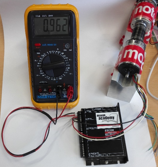
Figure 8:
Using an ESCON as a rectifier. Connect the 3 motor phases. No(!) power supply has to be connected. The generated voltage can be measured at the ESCON power supply input.
General remarks about controllers in "Generator" mode
- If the motor's voltage supplied to the motor connector of a controller (e.g. J2 of the "ESCON 50/5") gets higher than its minimum operating voltage (e.g. ESCON 50/5: 7V or 8V), the controller gets "alive" and is powered on by the generator's energy. The LEDs lit and the processor and control functions are activated. The power stage gets active too if it is enabled or based on some configuration.
- maxon controllers are not designed and not specified for this kind of operation. A simple 6 diode rectifier can do the same job too.
- The only advantage is that a motor controller (e.g. ESCON) will be able to limit the current and speed to protect the motor or some add-on mechanics depending on the controller's configuration and external signals.
- Note that there is a minimum speed (and resulting motor voltage) required before the controller is fully activated.
- If the generated voltage is always just around the controller's minimum required supply voltage limit, the controller's behavior might be quite unstable and unpredictable if it always switches on / off.
- Whether the generated voltage is finally sufficient for the controller's full operation including all protective features and outputs depends on the controller's internal hardware design and configuration too.
- The usage of a motor controller as one component of a "Generator" system can work depends on the configuration and generator speeds (resulting in a supply voltage level).
- maxon cannot provide a general recommendation for using maxon controllers as rectifiers for motors operating permanently in generator mode.
- maxon controllers have not been focused on "generator" applications in mind. There are also no such specifications or tests present by maxon.
3 Generator selection
When selecting maxon motors as generators a few rules should be respected. The special case of DC tacho is covered in chapter 3.4
3.1 Strategies for finding suitable maxon motors
DC or AC voltage?
Rule #1 follows directly from the theory of the previous chapters.
|
Rule #1 For generation of DC voltage select a brushed DC motor or use a brushless EC motor with voltage rectifier. For the generation of AC voltage, select a brushless EC motor and connect 2 phases only. |
Speed constant
Most generators are operated at speeds of 1000 rpm or below. That’s a low speed for maxon motors, which are made for high speed. Generating 10 V or more at 1000 rpm requires a speed constant of 100 rpm/V or less. Such windings are hard to find in the maxon portfolio. There are only a few high resistance windings on larger motors that satisfy this requirement. Smaller motors have higher speed constants.
Table 1 shows a selection of motors with low speed constant (or high generated voltage per speed). Usually, it’s the motor winding with the highest resistance only that result in speed constants of less than 100 rpm/V.
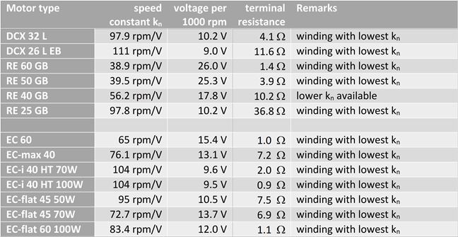
Table 1:
Selection of maxon motors with low speed constant.
|
Rule #2 Without considering the load, the winding should have a speed constant of |
As an alternative, the motor speed can be enhanced by the use of a gearhead, see chapter "3.3 Gear-motor combinations".
Resistance
Rule #2 requires motors with high generator constant. Unfortunately, these windings have the highest resistance as well. Hence, the output voltage is very sensitive to the load current.
However, there is another observation in Table 1:
The larger the motor, the lower the resistance for a similar speed constant.
|
Rule #3 For stable output voltage over a certain load range, select rather a larger motor where the resistance is lower even on motors with high generator constant. The EC-i 40 High Torque motors are very interesting from this point of view. |
3.2 Power restrictions
The same speed and torque restriction as in motor selection apply to motors used as generators. Respect the continuous operation range of the motor used as a generator.
Do not select the motor-generator on power considerations alone. In order to fulfill the torque requirements, you might need a motor with a much higher power rating than the generated power; in particular if the generator speed is rather low compared to typical motor speeds (compare the findings in chapter "1.3 Generator efficiency").
Torque and speed limitations
The amount of torque on the generator defines the size and type of the motor-generator. Select a motor type with a continuous torque rating higher than the generator torque.
When calculating the torque or current load, consider the type of operation:
Will the generator run continuously for long periods of time, or in intermittent operation cycles, or during short intervals only? Accordingly, a motor size with sufficient continuous torque or current has to be chosen.
Respect the maximum speed of the motor type. However, due to the generally low speeds this is hardly ever an issue.
Current and voltage limitations
The most appropriate winding of a given motor type follows from the current and generated voltage requirements. Select a winding that can generate the required voltage U even under load.
Assuming a fixed generator speed n we require generated voltage of the winding that is larger than U
Without considering the load, select the speed constant according to Rule #2, i.e. a winding with a sufficiently high resistance. Since the current capacity decreases with increasing resistance, verify that the continuous current is still large enough.
Figure 9 (below) quite nicely shows the ambivalent effects of different windings.
- The higher the winding resistance, the higher the generated (no-load) voltage.
- However, the higher the winding resistance, the more sensitive to load current changes the generated voltage becomes.
These contradictory effects can be eliminated to a certain extent by selecting larger motors that exhibit lower resistances for the same generator constant (according to Rule #2).
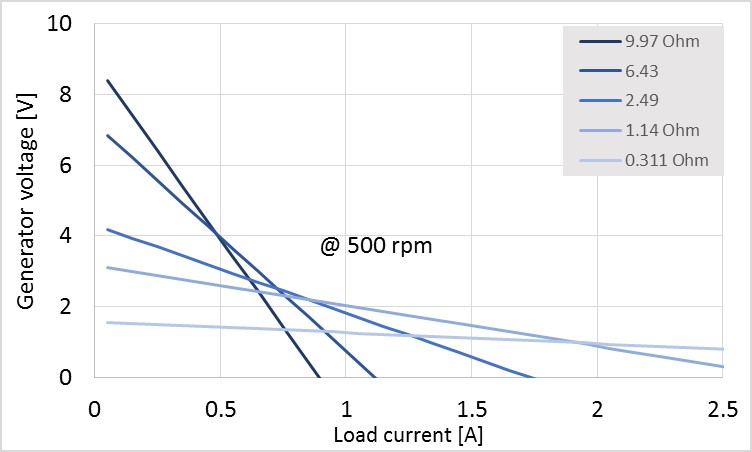
Figure 9:
The voltage-current lines of the different windings of the RE40 with precious metal brushes at 500 rpm.
Observe the different slopes of each winding.
3.3 Gear-motor combinations
|
Rule #4 Use gearheads to increase very low speeds. However, maxon gearheads are not really good in being driven from the output. Use gearheads that can be back-driven, i.e. planetary gearheads up to two stages or spur gearheads. Or specially designed gearheads with high efficiency such as the maxon Ultra Performance UP range. |
The reason for using gear-motor combinations is the very slow driving mechanism in generators; e.g. driven by a wind or water turbine or even by hand. A few observations and recommendations:
- The gearheads need to be driven by the output shaft in "generator" applications. However, maxon gearheads are not really designed for such reversed operation (by the output shaft).
- High reduction gearheads (3 stages and higher) are not well back-drivable; i.e. they will not turn when driven from the output with the maximum permissible torque. You may use 1 or 2 stage planetary gearheads; they can be operated from the output.
- Rather use spur gears instead of planetary gearheads. Spur gearheads can more easily be back driven.
- The maxon Ultra Performance (UP) planetary gearheads can be back-driven even with 4 stages due to their very high efficiency.
3.4 Special case: DC motor as DC tacho
|
Rule #5 For DC tachos, use motors with precious metal brushes. Select the winding according the required tacho voltage and the speed range in your application. Do not worry about the winding resistance, just make sure that there is a load resistance of several kΩ to keep currents small. |
In a DC tacho, the output voltage should be as proportional as possible to the speed, i.e. it should correspond to the generated voltage Uind. As noticed earlier, this corresponds to keeping Rmot * IL term small. The following points should be observed:
- Keep the load current IL small by using a large load resistance RL. Typically, a load resistance of several kΩ will reduce the difference between the internally generated voltage and the output tacho voltage to less than 1 per mill. Typical maximum motor terminal resistance values are in the range of several Ohms. When using a controller, check the tacho input resistance. For instance, on the ESCON the analog input resistance is 100 kΩ.
- Select precious metal brushes, which have a small and constant contact resistance. This is valid particularly at the very low currents that are to be expected when a DC motor is used as a tacho.
Please note:
Graphite brushes are not suited for DC-tacho operation and these low currents; the brush-commutator contact resistance being much larger than on precious metal brushes. In addition, the contact is very badly defined at low currents and the resistance varies a lot. - Select the winding according the required tacho voltage for the speed range in your application. If the output voltage per speed should be as high as possible, select a high generator constant, i.e. a small speed constant (rightmost motor winding by maxon catalogue data sheets). Which winding matches best has to be decided in each case.
maxon offers a standard DC tacho (DCT 22). Essentially, it is a precious metal DC motor with precious metal brushes and AlNiCo magnets. AlNiCo magnets exhibit the lowest temperature coefficient, which makes them perfectly suited for use in a sensor. The DCT 22 rotor is mounted directly on the motor shaft without additional bearings; therefore, avoiding a mechanically over-defined shaft with four bearings.
The nominal output voltage of 0.52 V per 1000 rpm perfectly fits to analog 5V sensor inputs of an electronics control up to maximum speeds of about 10’000 rpm; which corresponds quite well to the typical speed range of brushed motors.
Over the years, there have been other maxon motors with precious metal brushes (mostly the discontinued S motor series) in use as DC tachos.
Comments
0 comments
Article is closed for comments.