
Topic:
Why does the “CAN passive mode” error (0x8120) appear when I am using an EPOS4 and a CANopen communication bus?
Solution:
When the EPOS4 boots up it will check if at least one other CANopen device is present on the bus. If the EPOS4 does not detect any other device (e.g. a CAN master by its messages), the EPOS4 will change its state to so-called “CAN passive mode” and report the “CAN passive mode error” (0x8120).
The “EPOS4 Firmware Specification” (-> chapter “7 Error Handling”) states the following in case of a “CAN passive mode error” (Error code: 0x8210):
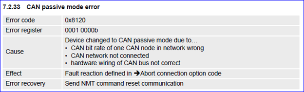
“CAN passive mode error” or even some other CANopen communication error states are mainly caused by one of the following root causes in practice:
- There is no other CANopen device present (e.g. no CANopen master).
This also means that the system will not work at all if no CANopen master is present to command the EPOS4 later on.
Remark:
The “CAN Passive mode error” can even happen if one EPOS4 boots up faster than other CANopen devices or the master. In this case the master can easily send a “Clear error” or NMT message to clear the “CAN passive mode error state” of the EPOS4. - The CAN bit rate configuration of the different CANopen devices does not match to each other.
This also means that the different CANopen devices will not be able to “understand” each other properly and there will be no reliable data exchange possible if the CAN bit rate configuration of the different CAN devices do not match. - The CAN bus network wiring is not o.k.
Please find some information about CAN bus topology and bus termination by this linked article:
-> CAN bus topology and bus termination
Root causes and measures
1.) CAN bus bit rate
The CAN bit rate can be set manually by the user or by setting the “Automatic bit rate detection” DIP switch or by object 0x2001 on the EPOS4 itself.
- Manual CAN bit rate configuration:
If the CAN bit rate is set manually, please make sure that this setting matches with the setting of the CAN master and other CANopen devices (e.g. EPOS4s) which use a fixed CAN bit rate configuration too. To check the CAN bit rate of the EPOS4 you can look at the object index 0x2001 using EPOS Studio’s “Object Dictionary” tool. - Automatic CAN bit rate detection
The automatic bit rate detection is pretty useful in applications where many CANopen slaves (or EPOS4) are present because the EPOS4 will listen for a data stream to identify and adjust its CAN bit rate to the one in use by other devices on the CAN bus.
Important:
If “Automatic bit rate detection” is in use, there has to be at least one CANopen device present which has a fixed CAN bit rate configured. Typical at least the CANopen master device uses a fixed CAN bit rate (e.g. 1 Mbit/s). If one EPOS4 serves as an USB/CAN resp. RS232/CAN gateway, this EPOS4 (or another one) needs at least a fixed CAN bit rate configuration.
Remark:
The problem with this setup shows up in a scenario where one EPOS4 boots up faster than the CANopen master or other EPOS4s. In this case the “fastest” EPOS4 listening for other CANopen devices does not find any because others have not fully booted up yet. Due to component tolerances the bootup time of different EPOS4s will vary slightly, this means that even in a network with lots of EPOS4 controllers there will be one which boots up faster than the rest and reports a “CAN passive mode error” because the network communication seemed not to be established then. The “CAN passive mode error” may be misleading in this case. The error state can be cleared by the master (e.g. by an NMT message). If the CAN bit rate configuration and CAN network wiring is o.k., the “CAN passive mode error” will not be triggered during operation then again. It is common good practice anyway that a CANopen master sends an NMT message after boot up at start of its application code and check error states after such a start-up code action.
2.) CAN bus wiring & termination
If the CAN bit rate configuration is o.k. and all drives have booted up but the “CAN passive mode error” is reported again after the master sends a “Clear error” or NMT command, it is very likely the CAN error state is due to a wiring issue which can be caused by …
- … loose connections.
- … flipped wires (CAN High / CAN Low / GND).
- … disturbed CAN signals by EMI
If there is an unshielded motor phase cable too close or on top of the CAN High and CAN Low wires, this can result in some so-called EMI (electro-magnetic signal interference). CAN frames might get disturbed or get lost then which can be a root cause of different kinds of CAN error states. - … wrong bus termination.
Checking bus termination:
To check the bus termination you will need a multimeter and have to measure the resistance in between the CAN High and CAN Low wire. You should measure a value of read around 60 Ohms.
- If it reads 120 Ohms, this means the bus is terminated on one side only or a lose connection exists somewhere.
- If it reads less than 50 Ohms, there might be wrong bus termination resistors in use or even more likely there are more than two termination resistors present. Please check the externally connected termination resistors and the DIP switch configuration.
- Important to know and check:
Please be aware that even in case of a measured correct value of 60 Ohms, the bus terminators can be placed wrong. Check and ensure that the bus terminations are placed at the both ends of the CAN network and not somewhere in between. - Remark:
CAN communication might even still work if there is just one CAN bus termination present and a low CAN bit rate configured (e.g. 125 kBit/s or less). Such an incomplete bus termination is not recommended and does not comply to the CAN standard. It is clearly stated that there has to be one bus termination resistor (60 Ohm) present at each(!) of the two end points of a CAN network. Please ensure that bus termination is done properly this way as the base of a reliable operation under all working conditions.
Comments
0 comments
Article is closed for comments.